- 您现在的位置:买卖IC网 > Sheet目录1991 > CS5509-ASZR (Cirrus Logic Inc)IC ADC 16BIT SGL SUPP 16-SOIC
CS5509
4
DS125F3
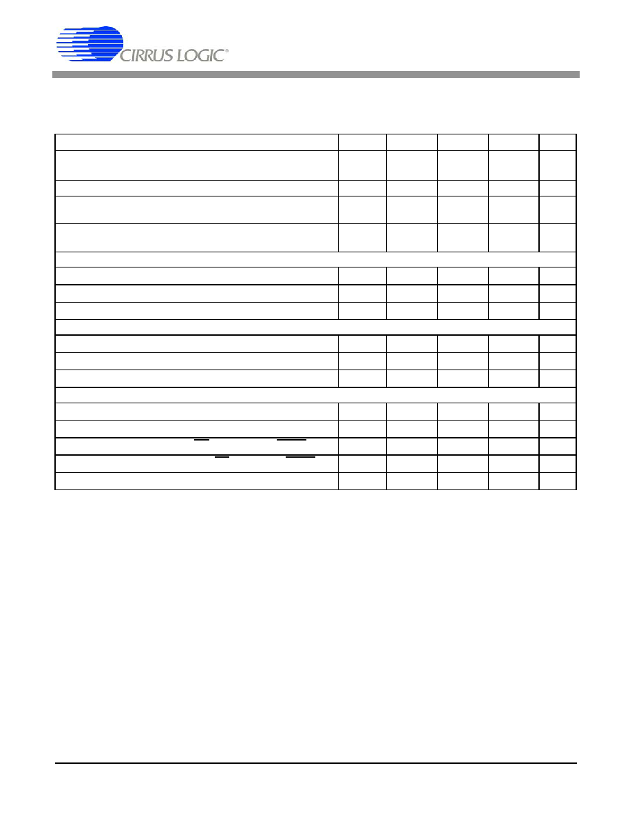
Notes: 10. Specified using 10% and 90% points on waveform of interest.
11. An internal power-on-reset is activated whenever power is applied to the device.
12. Oscillator start-up time varies with the crystal parameters. This specification does not apply when using
an external clock source.
13. The wake-up period begins once the oscillator starts; or when using an external fclk, after the power-on
reset time elapses.
14. Calibration can also be initiated by pulsing CAL high while CONV=1.
15. Conversion time will be 1622/fclk if CONV remains high continuously.
5V SWITCHING CHARACTERISTICS (T
A = 25 °C; VA+, VD+ = 5V ±5%;
Parameter
Symbol
Min
Typ
Max
Unit
Master Clock Frequency
Internal Oscillator
External Clock
XIN
fclk
30.0
30
32.768
-
53.0
330
kHz
Master Clock Duty Cycle
40
-
60
%
Rise Times
Any Digital Input
(Note 10)
Any Digital Output
trise
-
50
1.0
-
s
ns
Fall Time
Any Digital Input
(Note 10)
Any Digital Output
tfall
-
20
1.0
-
s
ns
Start-Up
Power-On Reset Period
(Note 11)
tres
-10-
ms
Oscillator Start-up Time
XTAL = 32.768 kHz (Note 12)
tosu
-500
-
ms
Wake-up Period
(Note 13)
twup
-
1800/fclk
-s
Calibration
CONV Pulse Width (CAL = 1)
(Note 14)
tccw
100
-
ns
CONV and CAL High to Start of Calibration
tscl
--
2/fclk+200
ns
Start of Calibration to End of Calibration
tcal
-
3246/fclk
-s
Conversion
CONV Pulse Width
tcpw
100
-
ns
CONV High to Start of Conversion
tscn
--
2/fclk+200
ns
Set Up Time
BP/UP stable prior to DRDY falling
tbus
82/fclk
--
s
Hold Time
BP/UP stable after DRDY falls
tbuh
0-
-
ns
Start of Conversion to End of Conversion
(Note 15)
tcon
-
1624/fclk
-s
发布紧急采购,3分钟左右您将得到回复。
相关PDF资料
CS5512-BSZ
IC ADC 20BIT EXTERNAL OSC 8-SOIC
CS5526-BSZR
IC ADC 20BIT W/4BIT LATCH 20SSOP
CS5528-ASZR
IC ADC 24BIT 8CH 24-SSOP
CS5529-ASZR
IC ADC 16BIT W/6BIT LATCH 20SSOP
CS5530-ISZR
IC ADC 24BIT 1CH W/LNA 20-SSOP
CS5534-ASZR
IC ADC 24BIT 4CH W/LNA 24-SSOP
CS5534-BSZR
IC ADC 24BIT 4CH W/LNA 24SSOP
CS5550-ISZR
IC ADC 2CH LOW-COST 24-SSOP
相关代理商/技术参数
CS5510
制造商:CIRRUS 制造商全称:Cirrus Logic 功能描述:16-bit and 20-bit, 8-pin ΔΣ ADCs
CS5510_09
制造商:CIRRUS 制造商全称:Cirrus Logic 功能描述:16-bit and 20-bit, 8-pin ΔΣ ADCs
CS5510-AS
功能描述:模数转换器 - ADC 16-Bit Delta Sigma ADC Ext. OSC RoHS:否 制造商:Texas Instruments 通道数量:2 结构:Sigma-Delta 转换速率:125 SPs to 8 KSPs 分辨率:24 bit 输入类型:Differential 信噪比:107 dB 接口类型:SPI 工作电源电压:1.7 V to 3.6 V, 2.7 V to 5.25 V 最大工作温度:+ 85 C 安装风格:SMD/SMT 封装 / 箱体:VQFN-32
CS5510-ASR
功能描述:模数转换器 - ADC IC 16-Bit 8-Pin Delta Sigma ADC RoHS:否 制造商:Texas Instruments 通道数量:2 结构:Sigma-Delta 转换速率:125 SPs to 8 KSPs 分辨率:24 bit 输入类型:Differential 信噪比:107 dB 接口类型:SPI 工作电源电压:1.7 V to 3.6 V, 2.7 V to 5.25 V 最大工作温度:+ 85 C 安装风格:SMD/SMT 封装 / 箱体:VQFN-32
CS5510-ASZ
功能描述:模数转换器 - ADC 16-Bit Delta Sigma ADC Ext. OSC RoHS:否 制造商:Texas Instruments 通道数量:2 结构:Sigma-Delta 转换速率:125 SPs to 8 KSPs 分辨率:24 bit 输入类型:Differential 信噪比:107 dB 接口类型:SPI 工作电源电压:1.7 V to 3.6 V, 2.7 V to 5.25 V 最大工作温度:+ 85 C 安装风格:SMD/SMT 封装 / 箱体:VQFN-32
CS5510-ASZ
制造商:Cirrus Logic 功能描述:A/D Converter (A-D) IC
CS5510-ASZR
功能描述:模数转换器 - ADC IC 16-Bit 8-Pin Delta Sigma ADC RoHS:否 制造商:Texas Instruments 通道数量:2 结构:Sigma-Delta 转换速率:125 SPs to 8 KSPs 分辨率:24 bit 输入类型:Differential 信噪比:107 dB 接口类型:SPI 工作电源电压:1.7 V to 3.6 V, 2.7 V to 5.25 V 最大工作温度:+ 85 C 安装风格:SMD/SMT 封装 / 箱体:VQFN-32
CS5511
制造商:CIRRUS 制造商全称:Cirrus Logic 功能描述:16-bit and 20-bit, 8-pin ΔΣ ADCs